from IPython.core.display import HTML
def set_width(width):
    display(HTML(f"""<style>
            .container {{ width:{width}% !important;
                            min-width:800px !important; margin: 0 auto}}
            .jp-Cell {{ width:{width}% !important;
                            min-width:800px !important; margin: 0 auto}} </style>"""))
# Set container width to X% of the fullscreen
set_width(50)
intro Function generator#
This intro supports labmanual 1B
A function generator is an electronic instrument that generates electrical signals of different waveforms. The most common signals produced are the sine, triangle, square and sawtooth shapes. With this instrument, it is possible to set the amplitude and frequency or your signal to any value in the operation range of the generator. The function generator used in this course has a frequency range of 1 µHz to 30 MHz for sinusoidal waves and an amplitude range of 10 mVpp to 10 Vpp.
Watch the following movie clip for an introduction to the function generator
Also have a look at the quick start manual: https://siglentna.com/wp-content/uploads/dlm_uploads/2017/10/SDG1000X_QuickStart_QS0201X-E01B.pdf
or the full manual: https://siglentna.com/wp-content/uploads/dlm_uploads/2024/08/SDG1000X_UserManual_UM0201X-E01H.pdf
## SCR-function generator
from IPython.lib.display import YouTubeVideo
YouTubeVideo('WFzjtMYQmSE', width = 600, height = 450)
Setting and using the function generator#
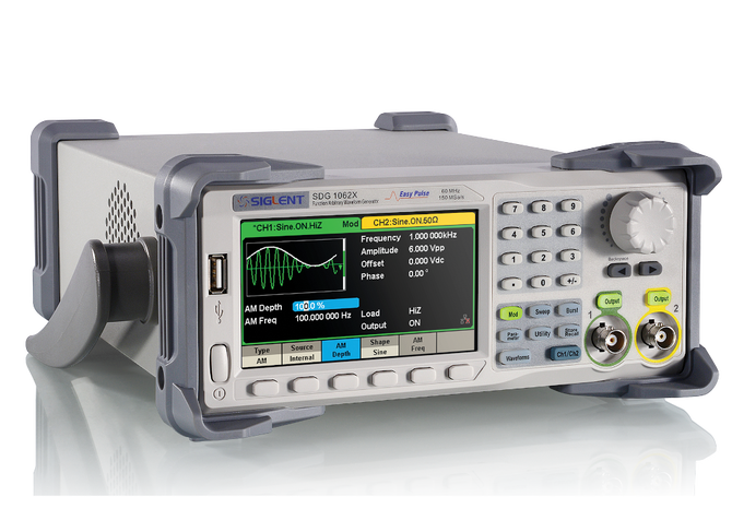
This Siglnet SDG 1032X function generator can generate the following (arbitrary) waveforms:
Sine
Square
Ramp
Pulse
Noise
DC
Arbitrary wave
You can adapt amplitude settings:
Amplitude & Offset,
High level/ Low level
You can adapt time settings:
Frequency / Period
Phase/ Delay
for square wave: duty cycle
After setting the correct settings for the waveform, connect the coax cable, and switch on the output
dual channel#
This arbitrary waveform generator can generate 2 signals at the same time. You can switch between the displays with the blue Ch1/Ch2 button.
coax cable#
Note: the BNC connector, and attached coax cable, have two signals. The signal line (inner core of the coax cable) is equivalent to the red wire from the previous exercise. The outer shielding is equivalent to the black wire/ COM. You therefore connect 1 wire, with 2 signal lines.
Harmonics#
For the sine wave, you can add Harmonics:
Type: even/ odd/ all
Order: 2-10
Harmonic amplitude
harmonic phase
You can use it to (try to) construct your own square wave, which consists off odd harmonics.
FG’s internal resistance#
The Function generator can be seen as ideal voltage source, with an internal resistance (inside the device). The generated voltage is then divided over the (fixed) internal and the external resistor (termed LOAD resistor; outside the device).

Utility - Output Setup#
Under Utility - Output Setup - Load, you find two options:
HighZ: default (e.g. upon startup), the function generator assumes an infinite load resistance (for example a DMM, or scope)
50 \(\Omega\): the generator assumes that the load resistance is 50 Ω (for example the rotary switch)
If the wrong load is selected, you might be off by a factor of 2 in the output signal.
FG trigger out#
If you only need one output signal, the second signal can be set to a square waveform, with for example 50% duty cycle. Such square wave can be function as output trigger.
output trigger from the rear#
Under Utility - page 2/2 - Sync, you can:
switch the output state On/ Off
change the type between CH1 and Ch2.
A 50 ns pulse will then be generated at the Aux In/Out on the rear panel. Such output pulse can be used to trigger the scope.